susie@jxgreentape.com
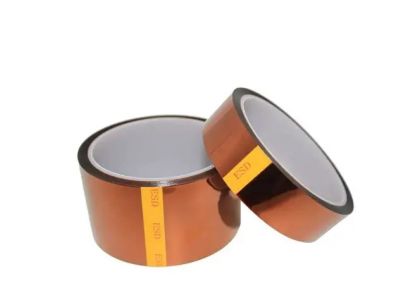
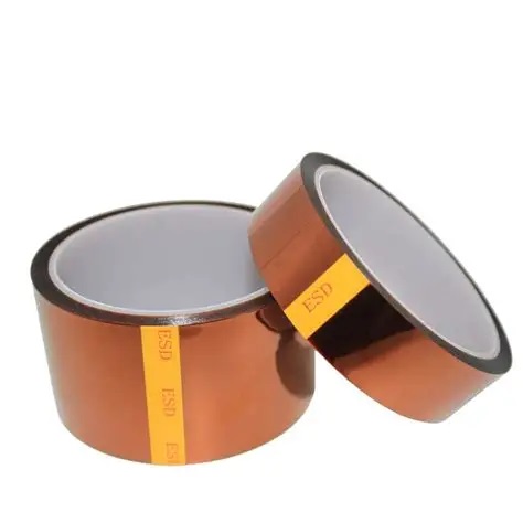
In modern PCB assembly, charged surfaces attract dust, pull flux residues, and create electrostatic discharge (ESD) risks that can damage sensitive components. When you mask areas of a board with Kapton-style polyimide tape, the tape's ESD behavior—commonly expressed as surface resistivity or surface resistance in ohms—affects whether the tape will safely dissipate charge or instead hold a charge that leads to surprises in the production line.
If your masking holds charge, you can see particulate buildup, unpredictable handling behavior, and even intermittent failures on low-voltage sensors. Specifying the right surface resistance is therefore a small change with outsized impact on yield.
Manufacturers typically specify ESD-treated polyimide tape with surface resistance numbers such as 10^6, 10^8, or 10^9 ohms per square. These numbers represent how easily charge moves across the tape surface:
10^6 Ω (one megaohm) — relatively conductive for an insulating film: charges can bleed away quickly, reducing triboelectric buildup.
10^8–10^9 Ω — in the static-dissipative window: it does not short sensitive nets but prevents persistent charge accumulation.
Analogy: metal is very conductive, untreated plastic is insulating, and an antistatic mat is dissipative. For many SMT and manual handling steps, the dissipative middle ground (10^6–10^9 Ω) is the safest choice.
A contract manufacturer runs a high-mix SMT line producing boards with low-voltage sensors and gold-finger connectors. They observed intermittent sensor failures traced to ESD events during manual masking. The CM tested two materials:
Standard Kapton (surface resistance >10^10 Ω): low cost but charged easily and attracted dust.
ESD-treated Kapton (surface resistance ≈10^8 Ω): slightly higher cost but eliminated intermittent failures.
They then placed an order from ESD Kapton tape supplier who provided full TDS and batch test records. With the new tape and a small operator training session on removal angle, first-pass yield improved and rework dropped.
To specify and verify surface resistance, use standardized test methods and a documented QC protocol:
Use a guarded electrode surface resistivity tester compliant with ASTM D257 or IEC 60093.
Test multiple samples per lot (≥5) and at multiple points (center and edge).
Control environment: typically 23±5°C and 50±10% RH—humidity affects readings strongly.
Record surface resistance and charge-decay times; some suppliers present decay time at a given voltage step.
Simple incoming test (example):
Condition samples 24 hours in lab environment.
Take 3 measurement points per sample.
Accept lot if median falls within 10^6–10^9 Ω and charge decay matches supplier claims.
Document these steps in your procurement spec so QA and suppliers measure the same thing.
Surface resistivity is only one axis—adhesive chemistry (silicone vs acrylic), adhesive thickness, and application pressure also matter:
Silicone adhesives: typically more heat tolerant and remove cleaner; their charge-dissipation behavior may differ from acrylics.
Acrylic adhesives: sometimes higher tack; can reduce lift during soldering but increase adhesive transfer risk if combined with near-insulating surfaces.
Match the ESD target to the adhesive: for manual handling or gold-finger masking, specify the 10^6–10^9 Ω window and test the exact adhesive/film combination you will use in production.
Many buyers work with an anti static polyimide tape manufacturer that publishes combined adhesive + surface resistivity test data—request those combined test results.
When you issue a purchase spec to vendors or evaluate a vendor, include these minimum requirements:
Surface resistivity range and specific test standard (ASTM/IEC reference).
Charge-decay performance under defined conditions.
Temperature rating and recommended maximum exposure.
Peel strength after heat exposure and adhesive transfer test protocol.
Batch traceability, TDS, and sample slit widths for automated feeders.
If you need slitted formats for pick-and-place or automated feeders, request quotes for ESD Kapton tape rolls for SMT with specified widths and tolerances, and ask for pre-slitted samples prior to bulk purchase.
A mid-sized maker received a shipment labeled "ESD-treated Kapton" from a new vendor. Incoming QC ran resistivity and peel tests and found surface resistance at 10^11 Ω—well outside the dissipative window—and stronger than expected adhesion after heat. They rejected the lot. Sourcing from an alternative ESD kapton tape manufacturer that supplied batch reports fixed the problem. After switching, first-pass yield improved 2% and costly rework was eliminated.
This simple incoming test avoided a production headache and saved money.
Storage and shelf life: ESD additives and surface treatments can change with humidity and contamination. Store reels sealed, use desiccants, and rotate stock (FIFO). Mark arrival dates and keep a sampled strip for periodic re-test—especially important if rolls sit idle for months.
Compatibility with conformal coating and solvents: test tape + adhesive + coating chemistry together. Some silicone adhesives resist cleaners better than acrylics but may behave differently in resistivity and peel tests.
Negotiation & contractual language:
Require batch-level test reports for surface resistivity and heat-peel performance.
Include acceptance/rejection clauses tied to measurable tests.
Clarify MOQ, lead times, and whether the supplier can provide ESD Kapton tape rolls for SMT pre-slitted to your widths.
Specify target surface resistance: 10^6–10^9 Ω and the measurement standard (ASTM/IEC).
Require TDS and batch reports.
Incoming QC: resistivity + heat-peel + visual.
Define storage, re-test intervals, and sample retention.
Order slit-roll samples for automated lines and verify adhesive + film behavior together.
With these steps, specifying ESD Surface Resistance for Kapton Tape becomes a clear, testable procurement requirement that reduces ESD risk and improves yield.