susie@jxgreentape.com
In global electrical manufacturing and maintenance sectors, engineers and procurement teams increasingly evaluate filament electrical tape not only for mechanical reinforcement but also for insulation reliability, documentation transparency, and long-term performance stability. When qualifying materials for coil wrapping, harness securing, and cable reinforcement, many buyers compare multiple suppliers before selecting the best filament insulation tape for their service temperature and aging requirements. In large sourcing programs, supplier comparisons often include production capacity, lead-time stability, and lot traceability across regions, including filament tape China supply chains. For long-term cooperation, working with a technically capable filament electrical tape manufacturer supports repeatability in electrical safety performance, adhesion stability under heat aging conditions, and consistent lot-to-lot quality control.
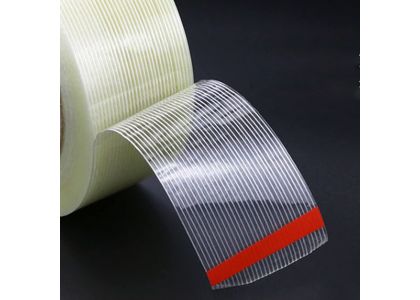
Unlike general-purpose adhesive tapes, filament electrical tape combines a polymer backing with embedded reinforcement filaments that improve dimensional stability and mechanical retention. In electrical systems, tape is often used to maintain insulation structure, restrain movement, and protect assemblies under thermal cycling and vibration. Reinforced constructions help reduce creep under load, which is especially important where position shift can compromise insulation spacing or mechanical stability.
Aging behavior is a central qualification factor. Electrical insulation tapes must maintain adhesion and structural integrity after exposure to heat and humidity. In motors, transformers, and electrical enclosures, long-term stability can be more critical than initial adhesion.
Reinforced tapes are widely used in industrial environments, but electrical insulation applications require performance verification focused on electrical safety and aging stability. Incorrect selection can create risks such as:
Electrical insulation applications typically require verification of electrical performance, aging stability, and mechanical retention, in addition to tensile strength.
Electrical insulation tape selection usually focuses on reproducible performance parameters rather than marketing descriptions. Commonly evaluated categories include:

Reinforced electrical filament tapes are commonly used across electrical manufacturing and equipment assembly sectors. Typical applications include:
Each application may require different backing thickness, adhesive system selection, and reinforcement orientation, depending on temperature exposure, vibration, and load direction.
For electrical insulation applications, product consistency is as important as nominal specification. Manufacturers typically focus on process controls that maintain electrical and mechanical reliability across production lots.
Common control areas include:
These controls support stable performance across repeat orders and multi-site qualification programs.
For insulation-critical work, filament electrical tape should be specified with a balance of electrical, mechanical, and environmental requirements. Clear specifications support consistent qualification and reduce application variability across assemblies.
|
Property |
Why it matters in electrical insulation |
Test / reference (examples) |
How it is typically reported |
|
Backing material |
Influences dimensional stability, handling, and aging behavior |
internal spec / supplier method |
backing type stated (e.g., PET film) |
|
Reinforcement type & orientation |
Determines stability under tension and vibration |
internal spec / visual inspection |
glass yarn reinforcement; orientation described |
|
Total thickness |
Affects conformability, wrap build-up, and edge behavior |
ASTM D3652 or supplier method |
mm (or mil) with tolerance |
|
Tensile strength & elongation |
Indicates resistance to tearing and loosening |
ASTM D3759 or equivalent |
N/25 mm and % elongation at break |
|
Peel adhesion (baseline) |
Indicates coating consistency and anchoring stability |
ASTM D3330 or equivalent |
N/25 mm with dwell time and conditions stated |
|
Holding power / static shear (at temperature) |
Indicates creep resistance under heat |
ASTM D3654 or equivalent |
time-to-fail under stated load/area/temperature |
|
Dielectric withstand / breakdown |
Indicates insulation safety margin under voltage stress |
buyer requirement / referenced methods |
voltage rating with stated conditions and criteria |
|
Insulation resistance (if required) |
Indicates leakage resistance under defined conditions |
buyer requirement / referenced methods |
resistance under stated conditions |
|
Heat aging performance |
Indicates retention after thermal exposure |
internal method aligned to buyer requirement |
before/after retention or pass/fail with duration |
|
Residue / serviceability |
Impacts maintenance and rework cleanliness |
internal method / buyer method |
substrate + aging + removal condition and observation |
Performance is strongly affected by substrate, surface condition, service temperature range, and dwell time after application.
A qualification-ready supplier typically supports electrical projects with documentation that can be reviewed by engineering, quality, and compliance teams. The package commonly includes:
Stable documentation structure and lot traceability support repeat orders and long-term supplier management.
Initial adhesion checks alone do not predict long-term performance under heat aging, humidity exposure, and vibration. Common failure modes include:
1) Heat-related creep and loosening
Sustained temperature exposure can increase creep under load. In coil wrapping or harness retention, creep can result in gradual loosening or position shift. Validation commonly includes static shear or creep checks at representative temperature and duration.
2) Edge lift after thermal cycling
Thermal expansion and contraction can stress edges and overlap areas. If edge lift occurs, it can expose insulation boundaries or reduce mechanical stability. Validation commonly includes thermal cycling exposure followed by inspection and adhesion retention checks.
3) Adhesion change after humidity exposure
Humidity and condensation can change bonding behavior depending on adhesive system and surface condition. Validation commonly includes elevated humidity exposure followed by peel retention or defined pass/fail inspection on the actual substrate.
4) Reinforcement orientation mismatch
If reinforcement orientation does not match the direction of stress, the tape can tear or fail unexpectedly during installation or vibration. Validation includes checking reinforcement orientation against load direction and verifying tensile behavior in the intended direction.
5) Residue or contamination during maintenance
Residue behavior depends on adhesive chemistry and aging conditions. Validation defines removal temperature/time and confirms residue behavior on the actual substrate and surface finish.
The best filament insulation tape for harsh conditions is typically the one that maintains stable retention after representative aging exposures, with acceptance criteria defined for both electrical and mechanical performance.
A qualified filament electrical tape manufacturer typically supports selection with stable documentation, defined verification conditions, and consistent lot traceability.
In electrical systems where heat aging, vibration, and long-term mechanical stress are present, reinforced insulation tapes provide value by combining dimensional stability with mechanical reinforcement and stable adhesion behavior. Filament electrical tape can support coil wrapping, harness retention, and cable reinforcement when it is specified with clear electrical and mechanical requirements and validated under representative environmental exposure conditions. Selecting the best filament insulation tape is a qualification decision based on defined test criteria, documentation readiness, and lot-to-lot consistency across repeat orders.
Define dielectric withstand (or breakdown) requirements under stated conditions, specify long-term service temperature and aging duration, and include creep/holding-power verification at temperature. Mechanical reinforcement and adhesion retention should be evaluated after aging, not only at initial application.
Compare reinforcement orientation, total thickness, tensile and elongation behavior, peel retention after aging, and holding power at representative temperature. Also compare documentation completeness (TDS/SDS), lot traceability, and change-control practices for repeat orders.
If the tape sits within insulation boundaries or near energized components, dielectric criteria are commonly required. Even when used primarily for retention, heat aging and creep behavior can affect insulation spacing and long-term stability, so verification beyond initial adhesion is typically necessary.
Substrate type, surface finish, surface preparation, application pressure, dwell time, and temperature/humidity exposure can significantly change adhesion and aging outcomes. Validation on the actual substrate and under representative conditions improves predictability.
At minimum: TDS and SDS with stated test conditions, material compliance documentation if required by the market (often requested for cross-border programs), a clear lot traceability method linking shipments to production records, and change-control procedures for material or process updates.